All the 3D printed parts are available on the Visit Site
Our robot’s body is 3D printed and made of laser cut plexiglass, which makes it easier to reproduce our work. The 3-layer plexiglass structure we used in the previous year cost us a great deal, because it was difficult to change batteries, and also made the robot too tall, therefore we opted for a box design.
It uses a Raspberry Pi 4B+ as its onboard computer. There were no issues with this single board computer in the previous year, aside from some rather embarrassing software problems that we detail elsewhere in our TDM. We initially planned on using the new Raspberry Pi 5, however its lack of hardware video encoding, availability and its newness in general were concerns for us, while its improvements didn’t really matter for our case.
The Pi 5 promises much better performance, PCIe, two DSI camera ports. None of our components use PCIe nor would they benefit from them (I2C’s 100kbit/s speed is more than enough). The better performance is always welcome, however the only code running on our robot is a daemon that receives commands via a TCP connection and controls our motors and arm (each command has been squeezed into a single byte), and an FFmpeg script that captures from a webcam, transcodes the video using the Pi’s hardware encoder and streams it over a TCP connection. The extra DSI camera port is pretty much moot, we can simply use an USB webcam.
The robot uses four DC motors for moving, a 20V drill battery as power supply. We designed a custom pcb for a stepper robot arm, but there were many issues with it so we use servo motors for the arm, a webcamera, and a metal robot arm. For motor control, we use a MotoZero. We use an MQ-135-M smoke sensor for CO2 sensing.
| Component | Cost (in Euros) |
|---|---|
| Raspberry Pi 4B+ | 71 |
| 4x JGA25-370 12V 60rpm | 34.58 |
| Parkside X20V Drill Battery | 42.16 |
| DCDC-6010-M, DC/DC step-down, max. 60V, max. 10A | 17 |
| Webcamera | 26.78 |
| 2x LT-623 | 4.23 |
| 2kg PLA filament for 3D prints | 40.5 |
| 4x Tower Pro MG995 | 32 |
| Adafruit PCA9685 servo controller | 13,77 |
| 6-24V 12V/24V to 5V 3A CAR USB Charger Modul | 3 |
| AX SS HYRAX crawler tire 120mm diameter 4pc pack | 30,52 |
| Overall cost of components |
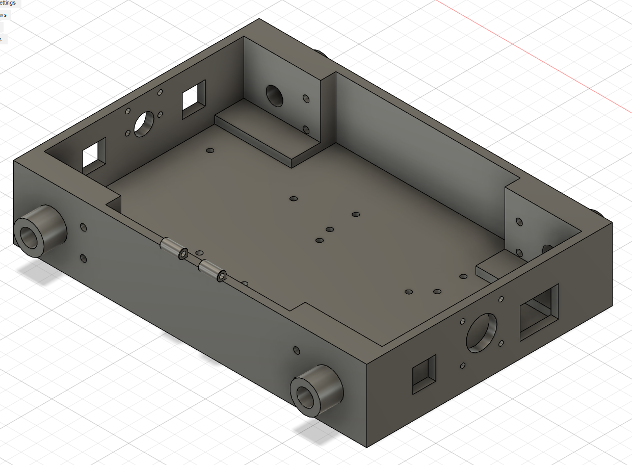
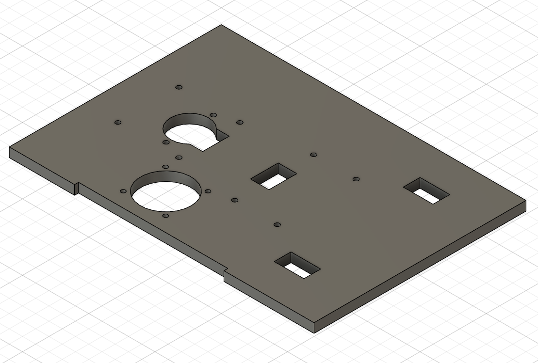
The frame of the robot
The frame of the robot is made of a 3d printed box with a lasercut plexiglass top. The body holds and give place to a Raspberry Pi 4, Adafruit PCA9685, and 2 buck converters for stepping down the voltage for different components. The motor holders are designed to fit in the box itself, because we wanted to make the robot's center of gravity as low as possible. The shafts of the DC motors that we use are supported by the casing of the robot so the hard terrain won’t affect the motor. We control the motors with a MotoZero with a heat sink which prevents the driver from overheating. We've also put a 40mm fan on the robot to make sure that nothing will overheat. The robot is powered by a Parkside 20V X20 drill battery. The holder for the battery is a 3D printed case. The motors run on 12V and the raspberry and robot arm runs on 5V that’s why we use one converter to get down to 12V from 20V and another one to convert it down to 5V.
Robot arm
The robot arm itself contains 4 Tower pro MG996R servos. At first we used 3D printed parts for the arm, but we had several issues with it. First the plastic melted, which was mainly our fault, because we gave the motors higher voltage than it was inteded. Then our second issue with 3D printed parts was the attachment of the motors. It broke very quickly so we decided to use metal parts in order to make sure that it won't break. The motors are controlled by an Adafruit PCA9685 PWM controller. It doesn't take up much space so much more efficient than our previous stepper motor controllers. The gripper of the arm is 3D printed, but we are planning on changing it to metal as well. The credit of the grabber goes to: Click here to view model.
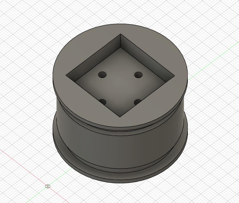
Wheels
We ordered 4 tires online but it was cheaper to 3d print the rims, so we designed it using CAD softwares. We 3D printed the rims and the motors' drives in one piece. The first problem occurred when the wheel broke at the base of the motor drive. So far we designed and made 4 different designs for the wheel. The current idea is to use metal and make a custom CNC motor drive.
Strengths and real-life applications
We focused on making our robot compact, easily manufacturable and well-rounded, with portable software so the same program can be ported to different single board computers.
What the team has learned so far
- We gained experience with Fusion360, TinkerCAD and 3D printing
- We learned about designing and assembling custom PCBs.
-
Using C enabled us to learn a lot about interacting with hardware at a lower level:
- Using standard Linux APIs
- Using I2C to communicate with integrated circuits
- Reading datasheets
- Learned to embed FFmpeg in C programs using their various libraries